Wednesday 10 April 2024

Final Pi Wars 2024 Blog Entry

It is late in the evening the night before the blogging deadline. So this is my final pre-judging blog entry. I am on holiday in an apartment with no TV. So I had no way to connect my robot to a screen other than to try and get it onto a WiFi connection and VNC onto it from my son's laptop (which I am also using to write this last blog entry). Without a screen to plug into the robot, I decided to try an idea I had but never tested before. I changed the mobile hotspot name on my mobile phone to the same network SID and password as the Makespace network. I then booted up the robot and it connected as it already had the Makespace network set up from working on it there previously. Next I connected the laptop to my hotspot. I just needed to know the IP address the Pi had been allocated. I could not ping it using <robotname>.local so I had to guess the IP. I checked what IP the laptop had on the mobile hotspot, and as the Pi had connected before the laptop I guessed it might have an IP address one bit lower that the laptop. This proved to be the case, and I was able to VNC onto the Pi and work on my code! 

Mostly progress has been in diagnosing why none of my I2C devices were working. After much head scratching I found a note on the Pimoroni website that the silk screen for the 8x8 TOF sensor I was using was incorrect on early boards, and it actually should say x29. The same I2C address as my IMU is using! The IMU can be configured to use x28, but that needs a soldering iron which I don't have with me this week. But at least I could confirm both sensors work when only one is plugged in at a time. I can work with that.

Next I discovered the 8x8 sensor example in MicroPython uses Numpy which is not in the Pimoroni Motor2040 firmware. Ulab Numpy is in the firmware for their Unicorn boards, so I was able to test with that. But in the process of flashing the firmware this wiped the filesystem on the Motor2040 with all my code on it! Thankfully I back things up pretty often. I had all the files on the Pi SD Card, and was able to restore them all apart from one. I managed to download that from my NAS at home over the internet. So everything is back in place. Unfortunately the Unicorn firmware does not contain the motor and encoder classes I need. A cry for help to Pimoroni software expert Gadgetoid resulted in him building a custom MicroPython firmware build which includes the ulab Numpy modules. Now that is customer service! He warned me it will wipe my filesystem, but as I've already been there I am good to try it. Except I had a blog to finish, so I've not done any more coding yet. Plus I am here to relax, after all!


Sunday 7 April 2024

My Robot is Hardware Complete!

 Finally I have everything assembled and wired up!


I realised my directly soldered wires were prone to snapping off the PCBs, and I needed headers to plug my servo motors into. Just having a pair of signal wires coming of the Motor2040 board was not going to cut it.


My solution was to design some additional brackets to bolt an I2C distribution board onto. A PCB I designed after Pi Wars 2019 but had never actually used on a robot until now.


This board has 4 pin sockets for I2C breakouts, along with some 5 pin sockets intended for the Pimoroni Breakout Garden boards which use a 5th pin for some other signal functions. This 5th pin for each of these sockets is connected to a header on my board. In a flash of inspiration I realised I could cut the power track to these 5 pin sockets, and by sacrificing 2 of these 5 pin outlets I could wire one of the spare 'signal' pins to V+ from the motor supply 6V line and one to GND. Then I could feed the servo supply voltage, GND and the RX and TX signals into this signal header and supply each of the remaining 5 pin sockets with high current power, GND and the signal line needed for the two servos. An extended custom lead crimping session saw the 2 servos converted to custom 5 pin JSH-PH plugs. A custom lead to supply the power and signal inputs to the board, and my servos were connected!

All that remained was to connect up the I2C input to the Motor2040 board and plug in my sensor and IMU and I was done. It was late in the evening the night before my week long family holiday and my robot was read to take away and maybe do some coding on in the evenings. Then the QWIIC socket broke off the Motor2040 board as I plugged in the final connector. I realised I it was too late to take everything apart again, and took the sensible option of going to bed to sleep on the problem.

In the morning, alongside final packing I managed to take apart the robot to remove the Motor2040 board. It has headers which can take a Breakout Garden socket (too large for the space I had) but also due to an extra GND pin on the header, could take a 4 pin JST-XH socket. Genius on the part of Pimoroni, or just good luck? Either way I was able to solder on a socket and crimp up one more custom lead and pack it all in my bag to take on holiday.


Monday 1 April 2024

Pulling it all together!

 A few more late nights working to assemble my robot. Thankfully the CAD model went together pretty well, with just some minor filing of parts to make them fit together well. I used hot melt threaded inserts in several places which makes it very quick to assemble (and more importantly take apart) when things go wrong.


Here you can see the lower chassis with the Motor2040 board mounted at the front with the battery tray in the middle between the wheels (the battery slides into this). The UBEC sits on top of the middle battery and the USB-C battery pack is on the back, held in place with velcro straps.


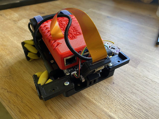
The 3D printed Raspberry Pi 5 case sits on top, screwed onto a pair of bars. The screws come up from below and hold the case together, so need to be fitted before the bars are screwed down onto the robot. You can just see the Motor2040 board below the Pi here with an IMU plugged into the QWIIC socket. It was at this point that things started to go wrong. See the yellow wire which has snapped off the IMU board where I had soldered it straight to the PCB. Then I realised my Motor2040 board has no servo headers. I have nowhere to plug in the servos on my grabber!


Some frantic study of the Motor2040 board documentation and schematic revealed no broken out pins from the GPIO. There were some analogue inputs, but it turns out these are for a seperate ADC chip and not the RP2040. Then I spotted the UART pins labelled RX and TX on the board. Looking at the schematic these are directly connected to a pair of GPIOs on the RP2040, and I was not using them for serial communications as I am using the USB socket for that! I clipped my PicoScope probe ground to the USB plug (the only accessible GND point with my board mounted) and found a simple servo driving example for MicroPython. Setting the RX and TX pins as the 'servo outputs' in the example I was able to confirm the PWM output on these pins on the PicoScope. The day was saved!

Friday 29 March 2024

3D Printing and Assembling my Robot

 Finally I have enough parts printed to start to assemble my final robot.


Some parts require supporting during the 3D printing process. I have an IDEX printer (Independent Dual EXtruder). This means it has 2 independent tool heads/hot-ends. They can each print a different material. So here I have printed my main part in PLA+, but used PETG for the support material. These different plastics do not stick together very strongly, so I can completely eliminate the vertical separation normally required to make supports removable. Above you can see the indented rectangles and the arch (this part was printed the other way up to how it is shown in the photo. The PLA+ is totally supported in these areas, and the PETG just snaps cleanly off (you can see the small PETG supporting parts behind on the desk).

Around 3 weeks to the competition and I have so much to do! I am away for a week around Easter too, so I have to turn this pile of parts into a working robot this week.


It isn't all advanced digital design and manufacturing. I cut these 'washers' out of plastic milk cartons as the polythene these are made of is really low friction. I put one of these between every pivot joint in the grabber so that the rougher surfaces of the 3D prints move smoothly over each other.

Monday 25 March 2024

CAD Model Completed

After several late nights working on my CAD model I think I have everything done.


Learning from past mistakes, I included a sketch of the maximum allowed robot size. I also used this to label which motor sockets on the Motor2040 board each of my wheels is connected to, so that I reassemble it correctly when I disassemble my test chassis and rebuild it with the 3D printed parts from this new design. I reused the Pi 5 case design, but reprinted it in better quality in ABS. I added mounting space for a USB-C battery pack which after testing I was happy to confirm is capable of powering the Raspberry Pi 5 with no issue. The twin cell Li-Ion battery pack between the wheels powers the motors (via a 6V UBEC) so they get a constant voltage supply whatever the level of charge of the battery. Using separate batteries also ensures the motors don't cause brown outs for the Pi power supply when the going gets tough.

The whole CAD design is highly modular. This enables each part to be printed separately, reducing the time lost if a print fails or a part needs modifying and reprinting. It also allowed me to get parts printing while I was still working on the rest of the model, saving valuable time.

Friday 22 March 2024

I really need to get working on my own robot!

Just one month to go until competition day, and I have not started building my own robot yet! Panic has started to set in and I have done some initial work on the CAD for a small chassis to hold the motors and a battery. Based on the design of my small tracked robot, but needing 4 motors instead of 2. I have a design which uses commercial camcorder batteries still commonly used for LED video panel lights. So they are easy to swap out and drop onto a charger.


I spent more time than I probably should on designing a model of the mechanum wheels. But now I have them to add to my common robotics parts CAD model library. I will share them on GrabCAD when I have time to think about things after the competition, so that other members of the robotics community can use them in their own CAD models. I'll do the same with the battery model. I have learned it really pays to model every component and put in all the machine screws and hex nuts in the CAD assemblies. This allows interference detection to be calculated and avoids costly mistakes which require re-printing parts when you discover a servo collides with a nut of some such problem when you try to assemble your design for real.

Friday 8 March 2024

Working on Attachments with my Young Persons Team

Since my holiday coding, all my Pi Wars time has again been spent mentoring my young person's team. Together we designed a barrel grabber to go on the front of their robot, and started 3D printing the parts for their proper robot. By the time we get to competition day, I will have built 4 robots in total! 2 test platforms and 2 actual competition robots. I am teaching my young persons CAD using SOLIDWORKS. We based the grabber off designs we saw when searching for robot claws on eBay and other direct from China tech selling websites. This is what we came up with.


But I have a cunning plan. Having 3D printed all the parts to fit onto their robot chassis, I am going to design the front of my own robot to have exactly the same mounting points. So I can print a second grabber, camera mount and sensor mounting block and put them onto my own robot. Hopefully this will not over balance my much smaller robot. I plan to put my battery on the back to act as a counter balance for the grabber.